Voltage and Current
Voltage and Current are electrical quantities that describe the potential (voltage) and the flow (current).
Voltage is often shown as E or V, and the unit is volts. It is measured with a voltmeter. In Europe, "U"[1] is used.
Current is shown as I, the unit is Amperes (or amps). It is measured with an ammeter.
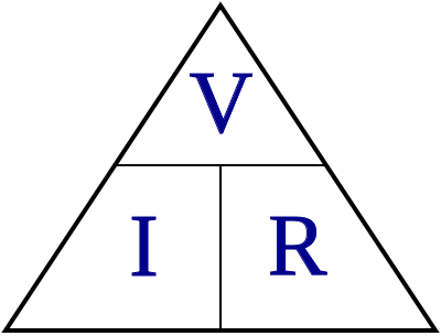
Ohm's Law describes the relationship between voltage and current in a circuit. The resistance of a circuit is determined by dividing the voltage by the current (E/I = R). Resistance is measured in ohms, the symbol is the Greek symbol Omega (Ω), and is measured with an ohmmeter. Ohmmeters are never used on energized circuits!
Ohm's Law describes how things will happen in a circuit, or is used to determine the quantities you should measure. This is useful for troubleshooting.
The Basics
Voltage
Voltage, or Potential, is analogous to pressure in a water pipe.
When water is stored in a tank, its mass will create pressure and push water out of an outlet at the bottom of the tank. The tank can be considered a battery, as it stores energy.
The unit is Volts. Sometimes called Potential, reflecting the fact that there is a difference in voltage between two points, such as the terminals of a battery.
Current
Current is the flow of electrons in a wire.
Current, measured in Amperes, is analogous to the flow of water in a pipe. Regardless of the pressure, the diameter of the pipe will limit the volume of water which can move through the pipe. Enlarging the diameter pipe allows for more volume. Where it may require two minutes to fill a container with water, reducing the diameter of the pipe will increase the time required to fill the container.
The pipe in this example fills the role of a resistor in electricity. A resistor will limit the flow of current, and a voltage can be measured across it, in accordance with Ohm's Law.
Voltage and Current
Now The Details
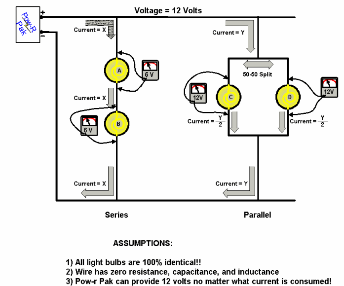
The picture shows a series circuit and a parallel circuit. This is how voltage and current are related in such circuits:
- Series Circuit
- The electrical current flows from the power supply into bulb A, out of bulb A and into bulb B, out of bulb B and returns to the power supply.
- The current flows single file through both light bulbs, and the light bulbs have the same resistance (assuming both bulbs are identical). Ohm's law tells us that I = V / R, or V = I · R, and since the current I and the resistance R are the same for both bulbs, the voltage drop of each bulb is also the same.
- Since the supply voltage is 12 V, that means there is a voltage of 6V across each bulb.
- The sum of the voltages must equal zero: +12 − 6 − 6 = 0.
- Parallel Circuit
- The electrical current flows from the power supply to the junction that leads to 2 identical light bulbs. The bulbs are identical, and they are both connected to the 12 V of the power supply. The missing piece of the puzzle is the current flowing through each bulb. Ohm's law tells us that I = V / R. Since the voltage V and the resistance R are the same for each bulb, the current I flowing through each bulb is also the same.
- The picture labels the current flowing into the parallel circuit with Y, so the current flowing through each bulb is Y/2. The total current is the sum of both lamp currents
General Rules
- Voltage
- In a circuit with two devices in series, the total voltage on the circuit is divided up between the devices. If the devices have the same resistance, there is half of the total voltage on each device.
- Current
- In a circuit with two devices in parallel, the total current flowing through the circuit is divided up between the devices. If the devices have the same resistance, there is half of the total current flowing through each device.
- Resistance
- The total resistance of resistors in series is the sum of the resistors.
- The total resistance of resistors in parallel: 1/RParallel = 1/R1 + 1/R2 +1/R3…
Power
Power is measured in Watts or VA.
The simplest way to determine power is to multiply the Voltage by the Current. The result is a unit called Volt-Amps or VA. This is true for AC (Alternating Current) and DC (Direct Current). Watts can be used, and often is with DC.
Power with AC is a little different: Another component, Power Factor, comes into play. With a pure resistance, the Power Factor (PF) is 1. Typically the load will be more complex, and introduce the power factor, which is the difference in degrees between the voltage and current.
The voltage will lead or lag the current, where the voltage will reach its maximum at a different time than the current. A very large power factor of 0.5 with a VA of 100 results in the wattage being 50. In this example the difference between the peak voltage and peak current is 60 degrees.
- Volts × Amps × PF = 50 × 2 × 0.5 = 100VA × 0.5 = 50W
- The power factor is the cosine of the angle of lead or lag.
What happened to the other 50W? It is an imaginary quantity called Volt-Amp Reactive, or VARs. It can be illustrated with the classic 3-4-5 triangle: 3 VARs + 4 Watts = 5VA.
Root Mean Square
Root Mean Square is the equivalent DC heating value of AC voltage and current.
It is a calculation designed to allow direct comparisons between AC and DC. Therefore 100W is the same, regardless of the power source.
As AC is a sine wave, its instantaneous value depends on the angle. A value of 100V RMS is 141.4Volts Peak (100 × √2) or 282.8V Peak to Peak. If the measured voltage is 200V-peak, the RMS value is determined by multiplying that value by 0.707 (or 1/√2), equalling 141.4V RMS.
The average voltage or current can be calculated by multiplying the peak value by 0.636.
While it may seem complicated, it makes it a lot easier when going from one world to another, particularly with respect to the conversion of AC to DC.
Quality multimeters will do this calculation internally and display the RMS value.
See Also
- Voltage (Wikipedia)
- Current (Wikipedia)
- Direct current (Wikipedia)
- Alternating current (Wikipedia)
- Ohm's law (Wikipedia)
- ↑ Unterschied, which means difference in German.


